Installation
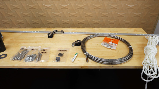
1) Review the parts list and make sure you have everything you need.
2) Thoroughly read the instructions, if you have any questions please reach out to us. You can contact us via phone or email.
Phone: 607-749-4599
Email: [email protected]
3) First we need to install the upper brackets, there are 2 top straps and a top bracket assembly.
3a) The mounting arms on the top bracket assembly must be formed to the mast to match the mast shape.
3b) You may need to form the top straps wider or more narrow to fit your existing masthead. Be careful to bend each Top Strap equally.
3c) The top straps are to be installed by removing either the backstay pin or the main halyard sheave pin. Install the top straps outside of your existing masthead using one of the 5/16” dia. Bolts provided (2” or 2 ½” long as necessary). Secure this with a 5/16’ dia. Nylock nut.
3d) Using the ⅜” dia. X 1 ⅞” long clevis pin, connect the top straps and top bracket assembly
3e) Swivel the top bracket assembly until the stop is against the mast. Center the bracket assembly on the mast slot. Drill and tap through the top bracket assembly into the mast. Fasten with ¼-20 x ⅜” long screws.
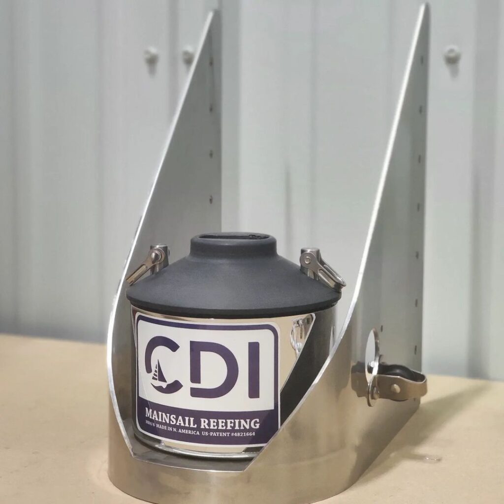
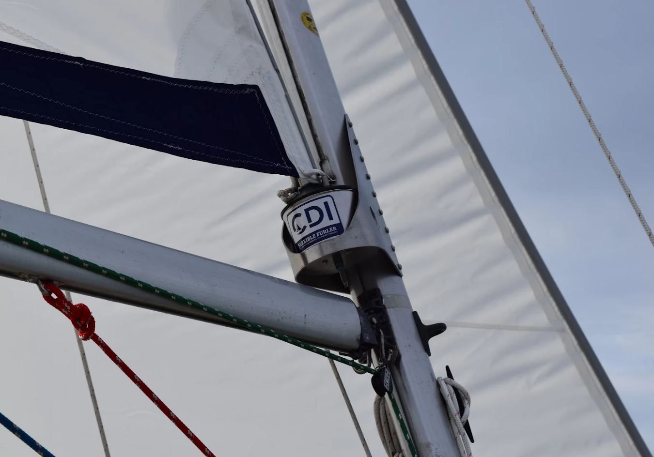
4) Next we are installing the lower bracket assembly. Including the lower bracket and the reefing spool assembly
4a) Match your lower bracket mounting surfaces to the approximate mast width. If the mounting services on the bracket need to be closer together place the bolting flanges in a vise and carefully squeeze them together until the width is correct.
4b) Centered on the mast slot, 2 ¼” above the top of the boom you will see the bottom surface of the Lower Bracket. Then find the bracket cup surface, perpendicular to the mast. If the bracket is not perpendicular to the mast the bearings will not freely rotate and it will always be difficult to turn the system. Against the mast you will find the bracket stop flange. Drill and tap through the bracket mounting holes and fasten with ¼-20 x ⅜” long screws. You will see two longer fixture screws included, these may be used to pull the bracket close enough to the mast that the correct ⅜” long screws will mount into the mast. To ensure that the holes line up, we recommend you install each screw as it’s hole is drilled and tapped.
4c) Now we need to figure out if the mainsail reefing line should be mounted on the port or starboard side of the boat. Mount the reefing line sheave on the lower bracket roughly where you want the reefing line routed. If the reefing line exits on the port side of the lower bracket, your UV shield should be sewn onto the starboard side of the foot and leech of the sail. If the line exits on the starboard side of the lower bracket then the shield will have to be on port.
5) Assembly of the mainsail reefing system internal stay.
5a) Measure the distance from the centerline of the lower pin in hte double jaw toggle part of the top bracket assembly and the bottom surface of the lower mounting bracket. Add 1 ½” to your measurement. This is the length of your internal stay, from the center of the top eye to the end of the threaded stud. Now cut the unfinished end of the stay and assemble the stay-lok eye in accordance with the stay-lok instruction sheet.
6) Installation of the reefing system
6a) Cut the luff to the length you calculated in step 5a, minus 8”
6b) Install a reefing line (3/16”) through the sheave on the side of the lower mounting bracket, through the hole in the side of the bracket, and finally up through a hole in the spool. Tie this off with a stopper knot in the end of the furling line
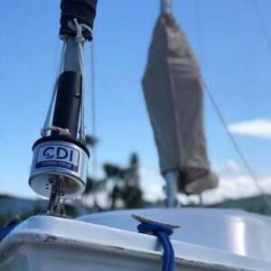
6c) With the reefing line attached, install the spool onto the bearing mounted inside the stainless steel cup which is located on the lower mounting bracket. Before raising the mainsail, wrap roughly 20 turns of the reefing line around the spool.
6d) To assemble the halyard top fitting onto the luff extrusion, first feed the de-cored end of the halyard down the luff groove opposite the sail feed slot. Now insert the stainless steel ferrule down inside the groove.
Then push the halyard top fitting over the top of the luff and secure it with the locking screw. Make sure the other end of the halyard, the end that does not have the ferrule, exits the top fitting on the same side as the sail feed slot and slides freely.
6e) Now we need to tie a messenger line that is roughly the length of the luff extrusion to the de-cored end of your halyard. We need this to raise the sail. The other end of the halyard must be pulled until the ferrule is hard against the halyard top fitting. Cut the halyard so that the sail’s head is barely below the sail feed slot in the extrusion. Melt off the end of your line to prevent fraying.
6f) Insert the bottom end of the mainsail stay through the halyard top fitting, luff, spool, and then through the lower bracket to finish. Place the bottom end of the luff extrusion into the spool.
6g) At the top of the stay there is an eye, insert the top bracket internal stay pin there.
6h) Under the lower mounting bracket we need to assemble three 5/16-24 nuts on the lower threaded end of the internal stay. The two nuts are to be used as jam nuts to hold the stay in place while tightening the tension on the stay with the third nut.Carefully, to ensure you do not bend the mast, tighten the stay until snug. Now we loosen the jam nuts and jam them against the nut already tightened to the stay.
7) At this stage we can take accurate measurements for a new mainsail. The exposed luff track is your new sail’s maximum luff. To measure the foot, we need the length from the luff sail track along the sail foot slot to the end of the boom, then subtract 6”.
Once you have measured for your new sail, you can remove the mainsail reefing system and use your old sail until your new sail arrives. Once the new sail arrives, we can continue the installation.
8) Installing the reefing track to the top of the boom
8a) At the outboard end of the boom locate the reefing track.
8b) Drill and tap through the mounting holes 10-32 threads into your boom, down through the former mainsail foot rope groove. Now we mount the track with 10-32 x 1 ½” long screws as each hole is drilled and tapped.
8c) Install the reefing car on the track
8d) Install the track end stops
8e) Install the boom reefing block with 1935 shackle, to the outboard end of the boom.
9) Install the correct lead blocks to lead the 3/16” diameter reefing line to the cockpit
10) Attach our 5/16” diameter outhaul line to the loop on the reefing car. Route the outhaul line from the reefing car up through your sail’s clew block, back through the block on the reefing car, then through the block on the outboard end of the boom, and finally forward along your boom to the mast.
Install whichever lead blocks are best to lead your 5/16” diameter outhaul line along the boom to the mast and then finally to the cockpit.
11) When running lines to the cockpit, route them to the most convenient place for you. Use some fairleads and take as few turns as possible. Increased friction from more turns than necessary will make the system more difficult to operate. Generally at least one winch should be used to assist in pulling the sail in and out. Many customers remove the main halyard winch and used for this. If you choose to run with one winch, a pair of jam or clam cleats should be positioned in front of the winch.
12) In most cases the main reefing system will not operate as easily as the jib reefing system because of the increased friction. When operating your winch, be cautious that nothing is binding and no lines are caught up on obstructions.
